FreeTrack Forum
FreeTrack Forum > FreeTrack : English Forum > Support : Tracking System > How critical are the dimensions?
| omarawatch | #1 19/01/2008 - 00h01 |
|
Class : Apprenti Off line |
I'd like to attach the 3 LED's to a standard headset - one at the top of the cranium, and one on each earphone. Is this a problem? Does this simply require more 'sensitive' of an adjustment? can I simply measure the dimensions and enter them once complete, or will I have usability problems if I don't follow the perscribed basic dimensions?
Your feedback is appreciated before I start building...... ~Brendan |
| Kestrel | #2 19/01/2008 - 02h30 |
|
Off line |
Since FreeTrack doesn't care what the real-world coordinates of the model are, the real size of the model is irrelevant, what matters is how big it appears in the camera frame. Too small produces poor rotation tracking resolution, too big and it can easily leave the camera frame for small translation movements. Size variations can be accounted for in the software.
The main problem with headphone mounted points, as you describe, is that the leds can be easily obscured by your head, keeping them visible for all head orientations will probably require extension rods away from the head. |
| omarawatch | #3 19/01/2008 - 08h13 |
|
Class : Apprenti Off line |
Well a 'headset' sized unit should be large enough based on your description.... so as long as they aren't obstructed from view, you
think any arrangement, as long as the measurements are accurate, will work correctly? My main concern is the how far 'back' the 3point hat design's top LED sits.... on a 'headset' design, it would be almost straight above the other two LED's mounted directly on each ear speaker.... please verify my thoughts before I start building.... Thanks so much, you are saving me lots of extra time/worry.... ~Brendan |
| Kestrel | #4 19/01/2008 - 08h22 |
|
Off line |
The middle led can be in the same plane as the others: http://forum.free-track.net/index.php?showtopic=515 |
| omarawatch | #5 19/01/2008 - 10h18 |
|
Class : Apprenti Off line |
While I believe you, the link you sent me appears to me, after my review, to have the top LED sitting well above and BEHIND the bottom two LED's, am I right?
If it doesn't matter and placement won't negatively affect performance, than I'll just build it, measure it, and then put it in the software  ~Brendan |
| tankbuster | #6 19/01/2008 - 12h53 |
|
Class : Habitué Off line |
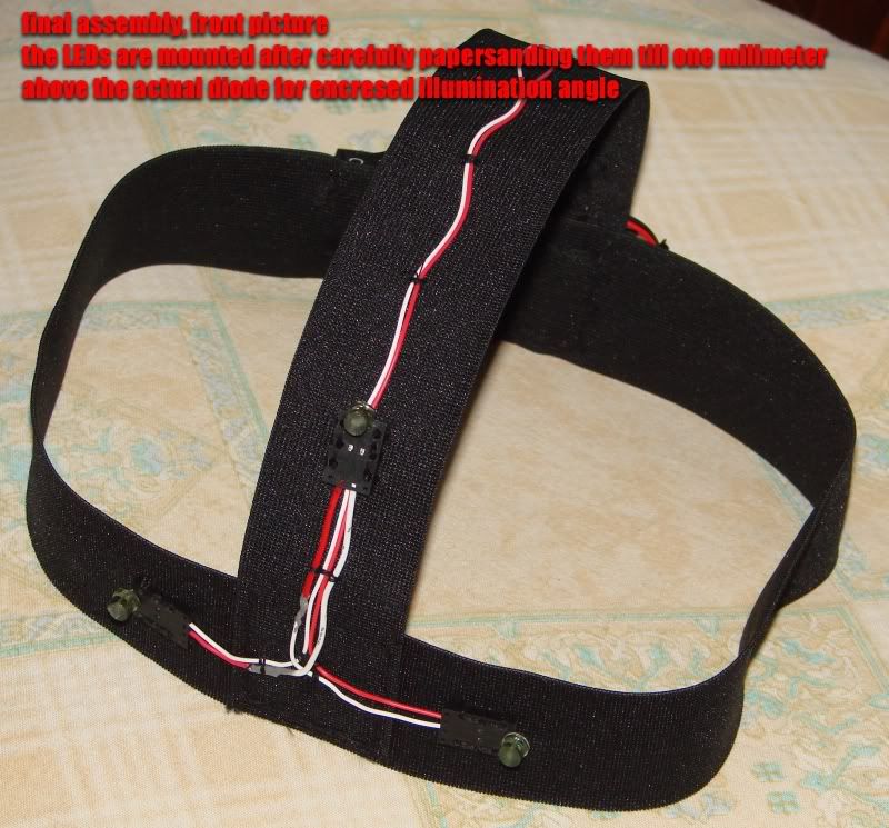
I'm currently building a headset (with microphone) mounted 3 point setup.
Kestrel is right when he says you need to be careful of occlusion - when your turn your head your skull obscures the emitters. For this reason, I'm making small plastic pylons (from this material) to move the emitters away and slightly forward of the headband. I did read that Kestrel said the initial dimensions given in the software itself are thought to be ideal so I'm sticking as close as I can to that but I'm going to struggle to get the top emitter 100 mm behind the other two. I think it's a good idea to mount on the headphones though because the rotation centre of your head is the neck joints so it more sense to have the emitters back near the ears rather than way forward hanging off a cap peak. |
| Kestrel | #7 19/01/2008 - 14h45 |
|
Off line |
You're right, I made my judgement based on this picture which, due to the camera perspective, looked coplanar. But note that in this picture the camera is looking down about 20-30 degrees at the point model, which reduces the depth of the middle point. |
| tankbuster | #8 20/01/2008 - 22h07 |
|
Class : Habitué Off line |
So Kestrel what about that top emitter... does it have to be behind the other two, or can it be level or even in front?
|
| zaelu | #9 21/01/2008 - 15h23 |
|
Class : Apprenti Off line |
In my case the top emiter is a bit behind the other two... in this picture is seen better:
http://i32.photobucket.com/albums/d36/zaelu/freetrack/DSC02749.jpg If you plan to mount them on an audio headset please note this observations of mine: 1. The head seat stays usualy more backward... or on top of the head which makes the lateral roatation harder to detect as the emiters are closer to the axis of rotation and have smaller arc of movement. 2. Although in theory you could set the top emiter in Freetrack settings to a 0 (zero) value for displacement from the plan of the front two, in my tests Freetrack becam sort of unstable when I introduced smaller values (2-4)! 3. You could mount the 3 emiters on a sort of "support" attached to the headset and make the support proportional but smaller than the recomended one (which emulates a hat dimesions). This is what a squad mate is trying to do but he has elbows in place of usual fingers so I expect a disaster  . .4. For headsets I think the 3 point clip is more suitable. IMHO Finally, another of my squad mates (this one has good fingers and is very good at electronics) has gone to your path (mounting them coplanar on the headset) and his first report was positive. Unfortunaly he has not reported to "airfield" for few days... maybe he "crashed" due to a mallfunction in this system . If I hear more news from him I'll let you know.His model can be viewed here: http://d13-th.ro/forum/index.php?showtopic=1515&view=findpost&p=39739 wait for page to load it gets you to his post (many pics)
Edited by zaelu on 21/01/2008 at 15h27.
|
| tankbuster | #10 22/01/2008 - 23h13 |
|
Class : Habitué Off line |
Is it possible to enter a negative figure in that field and build the top emitter in front of the two side ones?
|
| DPLUIGI | #11 25/01/2008 - 17h44 |
|
Class : Beta Tester Off line |
Allow me to plug in here. I am also in the process of building my first 3-points cap, which I'll follow with a 3-points clip. I have three questions about setup model size, accuracy and definition.
***1) About defining a point model*** I seem to remember that in Euclidean geometry (in two or three dimension) three distinct points defines a triangle and are always coplanar. When two sides have the same length then it is "isosceles" (two-fold symmetry) and "equilateral" (three fold symmetry) when three are identical. See http://en.wikipedia.org/wiki/Triangle for more about triangles. From a user interface point of view, wouldn't it be easier to define the "Model Dimension" in the "Setup" by the three lengths of the triangle formed by the LED in space or two lengths if a symmetry is assumed (i.e. isosceles triangle)? In the software these could be then translated in coordinates if needed. I am currently having a hard time setting-up the recommended coordinate on the model I am making. It is not trivial to measure and place the top LED 80mm back and 100mm from the mid-point of the bottom left and right LEDs. Measuring the distance between LED would be more straightforward, wouldn't it be?  *** 2) About model dimension *** Regarding the model dimension of the three point cap setup, I also found it difficult to place the top LED 100mm back from the other to. I am wondering if it would be equivalent to place it 100mm above and 80mm back instead? In term of coordinate using the coordinate system used in the 4-point Cap Model universal doc support.pdf (where Z-axis points towards camera and X is horizontal from right to left user shoulder)): The current default setup displayed in FRee-Track 2.1: Left (-70, 0, 0) Right (70, 0, 0) Top (0, 80, -100) would be: Left (-70, 0, 0) Right (70, 0, 0) Top (0, 100, -80) Does this makes sense and is there any reason it would not work?  *** 3) Accuracy *** Also, if I understand correctly the practical comment by Kestrel, the accuracy of the coordinate is not too critical (i.e. few mm accuracy is enough), is it not? Looking forward to your replies,  Thanks Donat-Pierre p.s.: I am wondering if I should have started a new thread in software/hardware here, which might have been mode relevant - I might link this post there.
Edited by DPLUIGI on 25/01/2008 at 20h52.
 |
| Kestrel | #12 26/01/2008 - 04h47 |
|
Off line |
A good idea, but more suited to the flat clip configuration, the cap model is tilted so you would also need to know the tilt angle. There's no question the dimension and calibration process could be improved.
If your measurements are different to the model, it only changes the rotation/translation sensitivity which is unimportant for normal FT use because sensitivity is adjustable anyway. The measurement process should be trivial. (The 3 point clip is a mild exception because it uses the dimensions of the model to try to cancel unwanted translation)
The point model dimensions are adjustable for this very reason.
Right, FT isn't trying to accurately locate the point model in real space, doing so would require the intrinsic properties of the camera (focal length, sensor size, lens distortion) which isn't necessary for bread and butter head tracking. Since rotation and translation observations only need to be relative the model dimensions are, in general, non-critical (within reason). |
| Kestrel | #13 12/02/2008 - 09h17 |
|
Off line |
Just to clarify, the tracking points should never be parallel to the camera plane because the pitching and yawing directions become unstable. This is expected due to the degenerate nature of the problem, the model's depth and consequently orientation, are uncertain, such that the equations have 4 different possible solutions. Some people have been experiencing this instability with models that have insufficient depth, where downward pitch is causing the points to become parallel to the camera plane (this is also when NAN errors occur).
Note that this only affects the 3 point cap; the 3 point clip isn't affected because the point plane is perpendicular to the camera plane, far from being parallel with it. The 4 point cap has an extra, non-coplanar point, so it is impossible for all points to be parallel to the camera plane. While this instability has tarnished the record of the 3 point cap for some, it can be easily avoided and the advantage of one less point far outweighs the disadvantages (TrackIR use this configuration). |
| RomD | #14 12/02/2008 - 23h36 |
|
Class : Apprenti Off line |
I tried moving the 2 front LEDs closer together and the back LED further back, but the headflipping problem remains.
The strange thing is that it only happens in one yaw direction. When I move my head in the opposite direction everything is fine. I noticed that when the head is upside down, one or two rotation values are equal to those of a total lock up. Kestrel, is it possible to test the new version with the applied NAN bugfix so I can check if it solves my problem? |
| Kestrel | #15 13/02/2008 - 01h25 |
|
Off line |
Then your model is degenerate and the front points are moving behind the middle point with respect to the camera plane. Check the dimensions you entered are correct and increase the depth and/or reduce the height of the middle point (as low as possible as long as the bill of the cap doesn't block it while pitching).
The tracking algorithm has to guess the orientation direction when a front point moves behind the middle point, it only guesses correctly for one yaw direction.
The NAN fix will not solve your problem, it prevents a lockup but tracking will still fail. |


FreeTrack Forum > FreeTrack : English Forum > Support : Tracking System > How critical are the dimensions?
> Stats
1 user(s) connected during the last 10 minutes (0 member(s) and 1 guest(s)).
Powered by Connectix Boards 0.8.4 © 2005-2024 (8 queries, 0.021 sec)