FreeTrack Forum
FreeTrack Forum > FreeTrack : English Forum > Support : Tracking System > 3-point clip vs 3-point cap
| Steph | #16 17/06/2013 - 08h37 |
|
Class : Moderator Off line |
For tracking with PS3-Eye disable all auto-function and colours to 0. Set exposure the way to get three good light dots and use threshold for fine tuning. What you see isn't IR-light, as this part of daylight normally is blocked by the IR-filter of the cam. Try with one more layer of coloured plastic sheet to eliminate rest-daylight . |
| doveman | #17 17/06/2013 - 12h58 |
|
Class : Habitué Off line |
Thanks for the tip, with an extra layer of the three coloured plastic it seems to be blocking all daylight now
 With the colours (White Balance) all set to 0 then nothing is picked up at all. I've uploaded some screenshots here: https://plus.google.com/photos/113676776900716988028/albums/5890425297469445553?authkey=COXwtszcmpe_fw The first one shows what settings I had to use to be able to see the LEDs OK in CL-Eye (this is all with the two layers of coloured film blocking daylight). The second is FT, with the White Balance sliders and Threshold at 0, where nothing is visible. The third is with Blue turned up slightly and as you can see, with the Threshold still at 0, this results in a lot of red noise, which I presume is internal electrical noise. Even with gain and exposure on 0, this happens although turning gain up to max I can see it gets somewhat redder. The fourth is with the the White Balance around 40%, Gain about 60% and Exposure near Max and with Threshold increased a bit you can just about make out the three LEDs amongst the noise. The fifth is with the Threshold increased further, when it starts to lock on the LEDs but also on random other points. The sixth is with Threshold increase further still, when it does mostly filter out random points and only lock on the LEDs but is unstable and keeps losing track of one or more (when this was captured the right one had just flickered off, although it still shows 3 green dots at the bottom). Increasing the Threshold any further and the tracking just gets worse and it loses all the LEDS. The seventh is in CL-Eye again, this time using the Camera settings I was using in FreeTrack. So I'm not really sure why it's not working properly for me. Certainly the dots from my clip seem to have been stronger http://forum.free-track.net/index.php?showtopic=3372&message=18644 which I don't understand. The only thing I can think to try (other than pulling apart the cam to remove the IR filter, which I don't really want to do) is to change the resistor to increase the LEDs output. |
| doveman | #18 17/06/2013 - 13h43 |
|
Class : Habitué Off line |
I checked by testing with the clip I made again and indeed the points are much better, so I thought what could be making the difference.
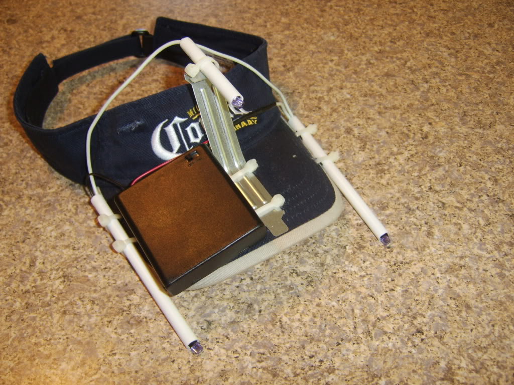
I've uploaded photos of the clip and cap wiring here: https://plus.google.com/photos/113676776900716988028/albums/5890446748063543137?authkey=CIfi3q3Xr4P2lQE I noticed I'm using thinner wire on the headphone/cap arrangement, so I thought I'd check the voltages at each point in case the thinner wiring was causing voltage drop. The results are rather confusing! With the clip I get: Before resistor - 4.88v After resistor - 4.23v After first LED - 2.82v After 2nd LED - 1.41v With the cap I get: Before resistor - 4.98v After resistor - 4.76v After first LED - 3.42v After 2nd LED - 1.32v I can't explain the higher voltage at the first two points with the cap, as I'm using the same phono connectors for the power-in socket but anyway, I'm getting better points with the clip even though it's starting with lower voltage, so that's obviously not important. With the cap I'm seeing 0.6v higher voltage coming out of the first LED compared to the clip (perhaps explained by the 0.53v extra going in) and 0.09v less coming out of the 2nd. So it seems the thinner cable I used for the cap isn't restricting the voltage at all, so I'm still stumped! |
| dewey1 | #19 17/06/2013 - 21h12 |
|
Class : Habitué Off line |
What are the resistor values for each?
What IR leds are you using for each? The voltages for the clip look about right. 1.41 x 3 = 4.23 4.88-4.23 =.65 with a 10 Ohm you have 65 mA af current. You should be getting close to same with the cap. What looks odd is the 3.42 volt measurement. Bad led or wiring problem!
Edited by dewey1 on 17/06/2013 at 21h38.
|
| doveman | #20 18/06/2013 - 01h48 |
|
Class : Habitué Off line |
I'm using a 10 Ohm resistor on both and the same LEDs, SFH485P. In fact, I took LEDs 1 & 2 out of the cap and put them in the clip, so only LED 3 was different and the clip works fine with them.
I see what you mean about the 3.42v, which gives a drop of 1.34v. I guess it should be 4.76-1.41 = 3.35v. So I know it's not the LED as that works fine in the clip, so I guess there must be something up with the wiring somewhere. I can't see how but I'll have to strip it down and see if I can find the problem. I guess I can't really test the wiring to each LED in turn as the circuit requires all three to be connected.
Edited by doveman on 18/06/2013 at 01h49.
|
| dewey1 | #21 18/06/2013 - 11h06 |
|
Class : Habitué Off line |
Remove LED 3 from hat and try it in clip. For reference purposes can we use LED1 as the one connected to the resistor, LED2 as the middle, and LED3 as the one wired to negative. Could you now restate the previouly posted voltage results of the hat in that format. Well with the clip you have a way to check your LEDs. Un plug one of those like the one wired to negative (LED3). Now plug in one at a time your unknown LEDs and measure LED3 voltage. It should be 1.3 to 1.5. |
| doveman | #22 18/06/2013 - 12h52 |
|
Class : Habitué Off line |
Yes it would have been sensible to swap all 3 LEDs wouldn't it  Anyway, I've done that now and they all work in the clip.
The differences I measured going into the resistor and before LED1 between the clip and cap seem to have been a glitch and they match now. With the clip I get: Before resistor - 4.98v After resistor - 4.76v LED1+ -> LED2+ - 1.32v (GND -> LED2+ -3.42v) LED2+ -> LED3+ - 2.10v (GND -> LED3+ 1.32v) LED3+ -> GND - 1.32v With the cap I get: Before resistor - 4.98v After resistor - 4.76v LED1+ -> LED2+ - 1.32v (GND -> LED2+ -3.42v) LED2+ -> LED3+ - 2.10v (GND -> LED3+ 1.32v) LED3+ -> GND - 1.32v So the voltages are identical. Having swapped all 3 LEDs between clip and cap several times now, I'm not sure there's much difference between the size of the dots, perhaps it's just that they're further apart with the cap or one was a bit nearer the camera. Anyway, I can't find any combination of settings which will solidly track them and even if it's fairly solid when idle, it tends to lose it when moving. So I guess it must be the IR filter that's preventing the cam from picking up enough IR to track them properly and I'll have to pluck up the courage to open it up and remove the filter. |
| doveman | #23 18/06/2013 - 13h26 |
|
Class : Habitué Off line |
On a separate matter, for the cap I want to make for my Dad, I was going to use a PC bracket like this for the vertical support http://www.free-track.net/images/point_model_gallery/specterm_11.jpg but the ones I have, which are standard PCI blanking plates, are only about 120mm long, so once I've bent it to go along the 65mm peak of the cap, the vertical (R) would only be 55mm high and I'm not sure that's high enough above the other two LEDs.
Assuming it is though, I've got some pre-bent angle brackets which are 60mmx60mm, so if 60mm high is sufficient I could use one of those to save having to bend the bracket myself. They also have holes in the middle which will probably help me to secure it in place. Looking at this model http://forum.free-track.net/index.php?showtopic=3624 it doesn't look like the vertical (R) is the default 100mm above the other two. So assuming my R is 60mm above the other LEDs and 70mm behind, what would be the best distance horizontally (X Plane) from R to each of the side points? I'd put them above the peak to avoid them being in the line of sight and have them protruding just forward of the peak to avoid the peak obscuring them when looking up. |
| doveman | #24 18/06/2013 - 18h06 |
|
Class : Habitué Off line |
I've tried the cap with a 6.8 Ohm resistor now and it's a bit better but still not usable. If I set gain and exposure to Max and White Balance to Auto it's a bit better but still loses tracking all the time.
I have added the extra layer of coloured film since my better results with the clip, so maybe that's blocking some IR light. I'll have to try going back to one layer to test. |
| doveman | #25 18/06/2013 - 19h15 |
|
Class : Habitué Off line |
It seems the coloured film is blocking some IR as well as daylight, as when I add the second layer it substantially cuts down the strength of the dots, so obviously one layer will be blocking a fair amount of the IR as well.
Nonetheless, when I was testing the clip before with one layer I was getting much stronger dots, using a 10 Ohm resistor and with the Threshold further right, than I am now with the cap using either a 10 Ohm or 6.8 Ohm resistor, which doesn't make much sense to me. Clip:  Cap:   |
| dewey1 | #26 18/06/2013 - 19h31 |
|
Class : Habitué Off line |
When you get the voltages as shown below then worry about the camera settings!
You have a bad LED 2, the 2.10 volt reading. How many LEDs do you have total in your possession? 
Edited by dewey1 on 18/06/2013 at 19h50.
|
| doveman | #27 18/06/2013 - 21h57 |
|
Class : Habitué Off line |
Thanks, yes I guess that should have been rather obvious  I bought about 10 of the LEDs, so I swapped LED 2 out and now it's producing nice distinctive dots like before with the clip I measured about 1.43v across each LED now. The pre-resistor voltage seems to have dropped a bit to 4.88v but I guess that's either because I'm using a 6.8 Ohm resistor now or else the supply from my hub must just vary a bit. It's tracking the two lower LEDs very well now, no matter what I do with my head but the top (R) LED is a bit more problematic, as it tends to lose it when I tilt my head back. I've tried angling the camera up more to try and keep the LED in view better but that doesn't really help and has the side-effect of making the lower LEDs go below the camera's FoV when I tilt my head forward |
| doveman | #28 23/06/2013 - 15h29 |
|
Class : Habitué Off line |
Whilst it's tracking the LEDs reasonably now, I'm still having a lot of problems using it in-game with DCS.
One thing is that if I'm looking straight ahead, turning left and right works OK but if I'm looking down a bit, it's reversed so that turning my head left makes the view go right in-game, which makes it rather hard to look at the controls! In FreeTrack I can see this happening, so that turning left when looking straight ahead causes the Yaw to increase in +ve numbers but when my head is tilted down, it goes the other way, into -ve numbers. It might be because it's not setup properly yet but I find it very hard to view a lot of the panels in the aircraft. Perhaps people use the snapviews in DCS for that and headtracking mostly for looking out the windows to check for enemies? |
| doveman | #29 26/06/2013 - 14h25 |
|
Class : Habitué Off line |
Anyone got any ideas why it's reversing the Yaw when my head is tilted forwards? I'm not tilting it loads, just what seems reasonable to look down in the cockpit, so I'd think it should be able to cope.
Obviously if I make it more sensitive so that I don't have to tilt my head as much to look down, it will be more jittery and react to small movements by pitching up or down a lot. |
| dewey1 | #30 26/06/2013 - 20h26 |
|
Class : Habitué Off line |
Is this with the hat or clip setup?
What are you using for the HOTAS or game controller? I have a button programmed for Tracker Center and Tracker Smoothing which helps out for Tracker in game control. A very good program for HOTAS or game control programming is called PGP or Pinnacle Game Profiler. I use this program on my F710 gamepad and my SRW-1 steering wheel. It gives you a lot of commands available that you cannot get on standard OEM software. I have one button dedicated to in game Freetrack control. I highly recommend it for the ultimate game controller software. http://pinnaclegameprofiler.com/features |

FreeTrack Forum > FreeTrack : English Forum > Support : Tracking System > 3-point clip vs 3-point cap
> Stats
2 user(s) connected during the last 10 minutes (0 member(s) and 2 guest(s)).
Powered by Connectix Boards 0.8.4 © 2005-2024 (8 queries, 0.025 sec)