FreeTrack Forum
FreeTrack Forum > FreeTrack : English Forum > Support : Tracking System > 3-point clip vs 3-point cap
| doveman | #1 03/11/2012 - 01h31 |
|
Class : Habitué Off line |
I'm planning to build a 3-point clip to go on the side of my headphones but I saw the comment in Freetrack "Webcam aligned with model" and wasn't sure what that meant. Does it mean the centre of the webcam lens needs to be in line with the reference point R as this could be a bit tricky to get exact without lowering my monitor, as my PS3 Eye is on top of it.
For the 3-point cap it says "Must ensure model plane does not parallel camera plane and I don't really know what that means either. Also, in the model dimensions for both clip and cap, it seems to allow me to enter anything I want, which I don't understand as don't the distances between points have to a certain ratio? Obviously I'd like to keep it as compact/unobtrusive as possible and I really like Steph's design here http://forum.free-track.net/index.php?showtopic=466&page=13#16602 so I just need to find the parts (I actually bought some straws after seeing another design but I don't really know how I'd put a curve/bend in the end of those), including a clothes hanger clip that will hold it tight in place on my headphones. For me, the clip onto the headphones is probably the trickiest part to work out. I also need to try and make a clip to go on glasses for my Dad, who doesn't use headphones when flying, although he might be OK with wearing a cap which would probably be easier. I like Rabb's reflective design though http://forum.free-track.net/index.php?showtopic=466&page=13#17224 and my Dad would probably be more accepting of something without wires trailing over his shoulder  I just need to see if I can work out a way that a clip can hold it firmly in place on the thin glasses leg. I just need to see if I can work out a way that a clip can hold it firmly in place on the thin glasses leg.  |
| Steph | #2 10/11/2012 - 15h19 |
|
Class : Moderator Off line |
Yes, you can  adjust orientation to the cam. adjust orientation to the cam. Also I never did, and my cam isn't exactly on axe and higher than the mount. It's not that significant.
I think that means, the reference point do not has to be on the same plane than the two others. (That happens when when the mount distance is very short and cam very high.) And the reference point may not go under the horizontal plane of the two other ones. (That happens when vertical distance between reference point and the the two others is very short and cam very low.)
As long as you respect the geometric proportions it's ok. But: Very small mounts are more sensitive and less accurate and very large mounts easily lose tracking. I would say: stay inside of the default dimensions +/-2cm is fine.
Tell me if you need some more photos on details. This tubes are Ø4 x Ø6mm polyamide tube like this ones used for pneumatic circuits. It has to be the hard one. I formed them with a hot air gun. Connection is a kite T-connector Ø6mm. |
| doveman | #3 10/11/2012 - 18h18 |
|
Class : Habitué Off line |
Thanks Steph. That clears up a lot of questions for me. Could you just give me the defaults for the 3 point clip and cap as I was playing around with them in Freetrack and the Default button is greyed out, so I can't click it to restore them!
Did I read somewhere that the polyamide tube can be found in aquarium shops? That might be the best place for me to try if so, to avoid having to pay shipping charges. |
| Steph | #4 11/11/2012 - 15h38 |
|
Class : Moderator Off line |
You can find them in the handbook.
Yes, polyamide or nylon, but it has to be really hard to stay in form. |
| doveman | #5 11/11/2012 - 19h47 |
|
Class : Habitué Off line |
Ah, OK thanks.
|
| doveman | #6 06/06/2013 - 09h09 |
|
Class : Habitué Off line |
It seems very hard to find polyamide tube online.
Maybe this nylon tube would be OK and it's available in 4x6 diameter in 1m lengths? http://www.ebay.co.uk/itm/METRIC-Flexible-Nylon-Pneumatic-Air-Line-Tubing-Compressed-Airline-Pipe-Tube-UK-/140707070015?pt=LH_DefaultDomain_3&var=&hash=item20c2cb803f or this http://www.ebay.co.uk/itm/Nylon-Air-pipe-Tube-Various-Sizes-1-metre-length-Black-/120848556117?pt=LH_DefaultDomain_3&var=&hash=item1c2322a055 You say it has to be really hard though and there's no indication of how hard it is, although maybe all polyamide/nylon tube is hard and I don't have to worry about that? For the Kite T-connector, I can find these on e-bay as well but mostly in 4mm and I imagine I need 6mm to fit over the outer diameter of the tube and these don't seem to be available http://www.ebay.co.uk/sch/i.html?_odkw=nylon+tube&_osacat=0&_from=R40&_trksid=p2045573.m570.l1313.TR0.TRC0&_nkw=kite+t-connector&_sacat=0 Otherwise I might have to look for alternative material to use, such as insulated copper wire, such as Rabb used here http://forum.free-track.net/index.php?showtopic=466&page=13#17224 For my Dad, who doesn't wear headphones, this design looks like it might be good http://www.free-track.net/images/point_model_gallery/falcon_02.gif and I guess thick rubber coated wire might be the same thing as insulated copper wire? |
| doveman | #7 07/06/2013 - 14h53 |
|
Class : Habitué Off line |
I've been trying to do the cap and coathanger method like this today
http://www.free-track.net/images/point_model_gallery/caothuvolam_01.jpg but finding it very hard work both to cut and shape the metal (just been doing the horizontal strip across the peak so far) and now I'm wondering why bother, as if I just glue the LEDs to the relevant points (I'll be using sockets made from an old IDE cable actually so I'd glue those rather than the LEDs) something like this http://www.free-track.net/images/point_model_gallery/volans_07.jpg won't it work just as well? I guess the only thing is that if the peak is bent more or straightened out, it will alter the distance between the LEDs and when the hat is put on, it could push forward the top LED, making it a bit nearer the other two but I don't know if these movements could be significant to worry about? Also, I was wondering if rather than wiring the LEDs in a chain like this http://www.free-track.net/images/point_model_gallery/specterm_12.jpg they could be wired so that the negative lead of the first LED is connected to the positives of both the other LEDs and then both of the negatives of these two LEDs taken back to ground, or is it essential that each LED is chained to the next one and that only the last one is wired back to ground? |
| dewey1 | #8 07/06/2013 - 23h37 |
|
Class : Habitué Off line |
Absolutely not!! Just wire it as shown. Why question a proper wiring diagram? |
| Steph | #9 08/06/2013 - 10h11 |
|
Class : Moderator Off line |
Yes. |
| doveman | #10 08/06/2013 - 16h42 |
|
Class : Habitué Off line |
Interesting, two contradictary answers
I was only asking out of curiousity as I was thinking, with the cap model, it might be possible to take the power in to the top LED and then use the metal bars to carry the +ve forward from that to the other two LEDs by wiring the appropriate legs of those to the horizontal metal bar across the peak of the cap and then connect the two returning -ve leads in the middle of the peak and take a single wire from there back up the middle to the top of the cap where the power connector is. That way you don't have two leads going down carrying the +ve forward to each of the LEDs, or two -ve leads going back up, so keeps it a bit tidier. I saw a design that uses a PCI slot blanking plate for the vertical support/mount and that seems like it might be quite easy and will keep the top LED in the correct place, so I'll probably give that a go as I'm sure I've got loads of those blanking plates lying around but I probably won't use a metal bar/coathanger across the peak as I found it rather hard, so will just put the LEDs in tubes (such as empty pens) and ziptie those through the peak of the cap to hold them steady. http://www.free-track.net/images/point_model_gallery/specterm_11.jpg |
| dewey1 | #11 08/06/2013 - 22h04 |
|
Class : Habitué Off line |
You asked two separate questions!
You got two separate answers so it is not contradictory!!!!!! |
| doveman | #12 09/06/2013 - 19h20 |
|
Class : Habitué Off line |
Sorry, my mistake, I got confused  Guess I should only ask one question at a time Guess I should only ask one question at a time |
| doveman | #13 14/06/2013 - 18h51 |
|
Class : Habitué Off line |
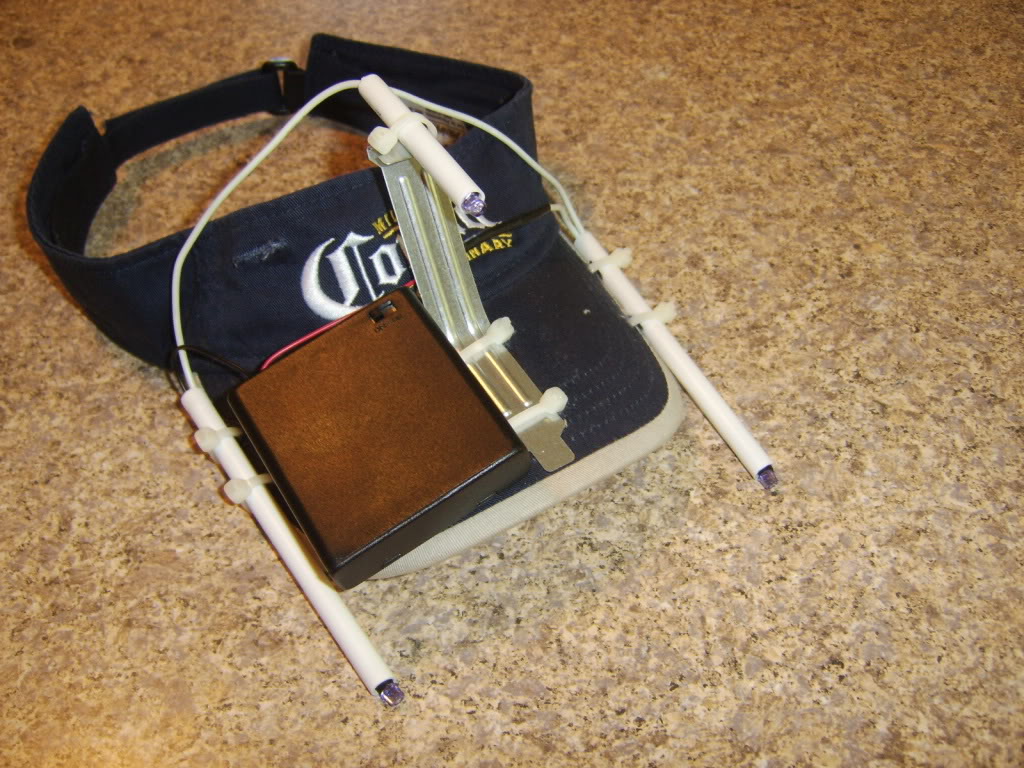
OK, I've knocked up a 3-point cap style arrangment but on my headphones, so I've got the R point on the top, above the middle of my head and the other two points just above the earcups on each side. I took a photo
http://img153.imageshack.us/img153/488/w2u.png Rough measurements give 102mm depth (z-plane) from the R point to the other two points and 95mm vertically (y-plane). From the R point to each of the side points it's 130mm width (x-plane). When I enter these numbers, it warns me that "Tracking is unreliable when a forward point moves behind the middle point (when yawing). Avoid by keeping depth greater than width". I can't move the side points inwards, other than moving them up the metal bars, which would greatly reduce the vertical distance (y-plane) from the R point to the other two. I tried testing it anyway and it's not tracking properly. It might be because it's still light outside, as I had problems with the clip in the daytime because of light from outside but with the clip it did track but just lost track when I turned right, towards the window. With this headphone clip, it's almost impossible to get it to track all three LEDs, particularly the top one (I suppose because it's further back). I can just about get it to pick them up with the Threshold as shown here sometimes but then it will keep losing track with my head still and definitely when turning it.  Earlier, when it was lighter outside, the camera was showing the orange coloured light coming through my closed curtains and I could even see my face to some degree (you can still see it a bit in the screenshot below), which seems strange as I'm using the three coloured filter to block everything but IR. This is what it looks like now that the sun's gone done a bit, in CL-Eye test with Gain and Exposure on Auto, which is basically Max right now and the colours on about 40%.  One thing I thought is that if the PS3-Eye does have an internal IR filter, then even though I'm blocking everything but IR with my external coloured film filter, it's going to have trouble picking up the LEDs, although perhaps the Threshold adjustment should be sufficient to enable it to track them. If I did remove the IR filter, then perhaps that would make it better able to track the LEDs, especially in daytime but as the camera seems to be picking up IR from the daylight outside, maybe removing the filter wouldn't help as the IR from the daylight would also be more visible and this might drown out the LEDs, as it appears to be doing now. Unless I'm completely wrong and the orange light from the window and illuminating my face isn't IR at all but normal light and it's just that my coloured plastic daylight filter isn't that effective and is letting it through. Maybe I should replace the 10Ohm resistor with a 6.8Ohm one to boost the LED output. |
| Steph | #14 16/06/2013 - 10h33 |
|
Class : Moderator Off line |
Make sure that you use the right dimensions. This is what they relate to: (So 102mm for z is certainly wrong)  (You need to set up your own measurements of course.)
Edited by Steph on 16/06/2013 at 10h38.
|
| doveman | #15 16/06/2013 - 11h00 |
|
Class : Habitué Off line |
No, 102mm is about right on my build for the distance you've got there as 130mm (maybe that's not the z-plane though?). My R point is not above the center of my head but more forward than you've shown it.
What do you think about the brightness/IR filtering? |

FreeTrack Forum > FreeTrack : English Forum > Support : Tracking System > 3-point clip vs 3-point cap
> Stats
1 user(s) connected during the last 10 minutes (0 member(s) and 1 guest(s)).
Powered by Connectix Boards 0.8.4 © 2005-2024 (8 queries, 0.026 sec)