FreeTrack Forum
FreeTrack Forum > FreeTrack : English Forum > Support : Tracking System > Your point model constructions
| DrSnow | #91 16/07/2009 - 21h02 |
|
Class : Apprenti Off line |
Finally got the pics in here.
My two versions: Cap: Osram SHF485P ir leds. Wirings and resistor inside linings. All joints soldered and covered with shrink tubing. 9 volt rechargeable battery operated. Attached to back of the cap with velcro. Used for almost a year now, very reliable and stable to use. Clip: Clip bent and cut from aluminium tube (used for example in rc car frames). All wirings and such inside the tube. Attached to headset by tension relief and wire clip. (another type of mount under development) Osram SHF485P ir leds. Changeable or replaceable by another type without soldering. 3 meter power cord. 9V rechargeable battery operated. Packed in a small box with connector outlet, power switch, and variable resistor for easier test setups. Used for 3 months now,. Very light, easy and reliable. ...my favorite.   Camera is Microsoft VX1000. Ir modded. Snow |
| brainload | #92 18/07/2009 - 16h24 |
|
Class : Apprenti Off line |
Mine is here in my facebook album: http://www.facebook.com/album.php?aid=89867&id=681679165&l=6314eee9ff
If anyone wants, I can buid some for resonable price with all equipment (AAA rechargeable batteries and recharger). Just drop me an email to tomas.vosahlo at email.cz |
| thagerty | #93 01/08/2009 - 13h50 |
|
Class : Apprenti Off line |
Here is my Freetrack Cap using.... Kinex!
 My Wii Remote Stand using Dollar Store camera stand and carboard box: 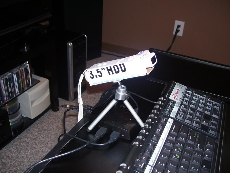 And my Car / Flight Simpit that I use it with: 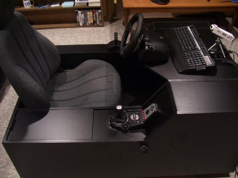 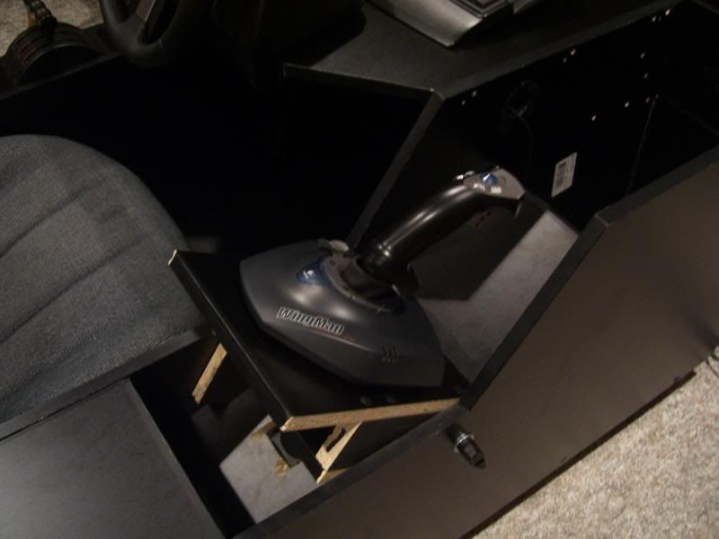 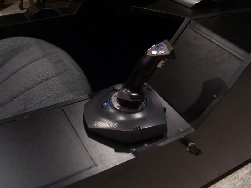 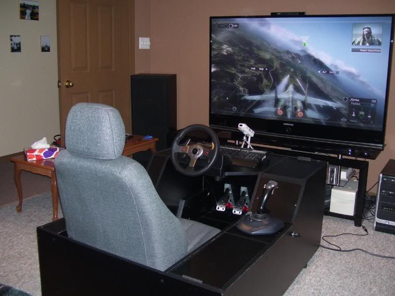 |
| WilderPilz | #94 04/08/2009 - 11h51 |
|
Class : Apprenti Off line |
More Setups
Here the Cap I used... Power: 9V Leds: 3x5mm (not flat), 1,2V, in Row; Dont know the Resistor any more Now I run this Cap with a 12 V Power Supply (Way too much) Resistor: 220 Ohm  I use a Microsoft VX3000 (IR Filter removed) - This is a very bitchy cam, need a lot of tweak to run perfect. I added a light Filter, based on the "Light Filter Mod MS VX****" in this Thread! http://forum.free-track.net/index.php?showtopic=845&page=1#6221 This Filter is very nice because you can remove it! A Floppy Disk is used as Filter.  And here we have another Setup. A Vertical one. I was inspired to build this up on this Thread. For Configuration Read this Thread (Easy HowTo) http://forum.free-track.net/index.php?showtopic=1856 The final connection to the Battery is missing. I did this in just 2,5h including collecting all the stuff in my place. The Cap I used, my first build, took me round about 1 day to assamble. Pros Vertical Setup - Very easy to build - Very light; also with Batteries - Easy switching LED´s - Perfect Tracking function (I compared it to my other Setup: Vertical Setup is better than triangla Setup) For Beginners this is pretty perfect, because you can tweak your Setup very easy. If you think about an alternative Power Source you can use a Power Supply or use a USB Cable (NOT FOR BEGINNERS!!!!!). Read the Documentation (Manual) in your Freetrack folder for this!!!!! Remember, if you switch your Power Source you have to use other Resistors!!!!!! Remember: If you use a Power Source with more Voltage you need to burn this Energy in the Resistor, because your LED´s are only running with 1,2 - 1,5V. The Resistor will waste the Energy so the LED´s will run in the perfect Voltage. More Voltage --> upper Resistor --> More Heat!!! And some Pictures    Thanks to the whole FreeTrack Team... You Guys are doing a great Job....  |
| mrclean816 | #95 07/08/2009 - 02h11 |
|
Class : Apprenti Off line |
My new clip. Coat hanger with some plastic and a paper clip.
     |
| Cockroach | #96 30/08/2009 - 20h06 |
|
Class : Apprenti Off line |
Congratulation DrSnow, they are amazing pieces. I really like your 3 point clip soluiton.
Mine is little bit more basic, with much stress on it being a "clip". 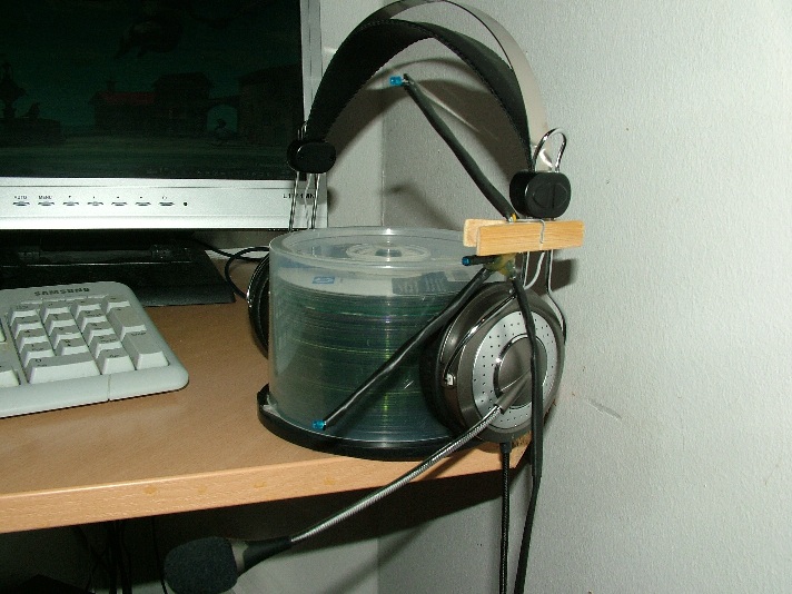 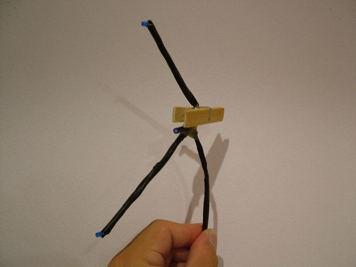 I am not sure on the exact type of LEDs, theye were the only accessible 3mm IR LEDs in my vicinity though. I used simple wires covered with shrinking tube as the support, connected the LEDs linearly and added a 27 Ohm resistor... Power supply is USB. The little bump on the lower part is the resistor beneathe the second layer of shrinking tube protecting the wireing. I regret now not using a method which makes the change of LEDs easier. Maybe next time... |
| teo | #97 03/09/2009 - 10h22 |
|
Class : Apprenti Off line |
Check this out!!!
   |
| lukinhasb | #98 14/09/2009 - 18h39 |
|
Class : Apprenti Off line |
content removed by the user
Edited by lukinhasb on 24/06/2010 at 17h20.
|
| thagerty | #99 19/09/2009 - 18h34 |
|
Class : Apprenti Off line |
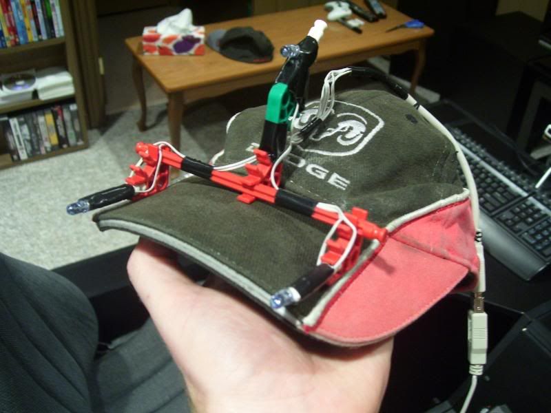
Here are some pics of the small updates I made to my Car / Flight Simpit and Freetrack hat...
Here is my new switch panel that allows me to turn on/off everything that's hooked up to the USB hub. Some games need to have only the wheel plugged in... or the Throttle may cause a prolem for another game,etc... Also has a key lock to lock out everything... and now I have a spare USB connector (hidden under near the wheel clamps) for I-POD,etc... 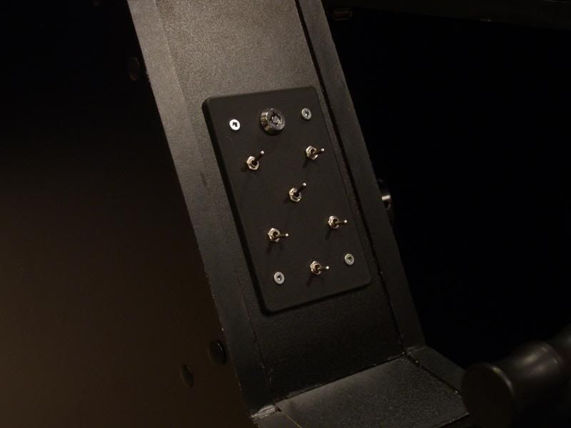 Now the usb hub and wires are all contained inside so the only visible wire is the keyboard and power bar. 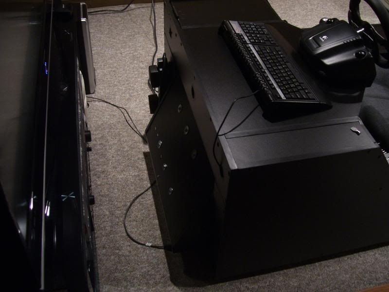 The Wii-remote stand is all black now... 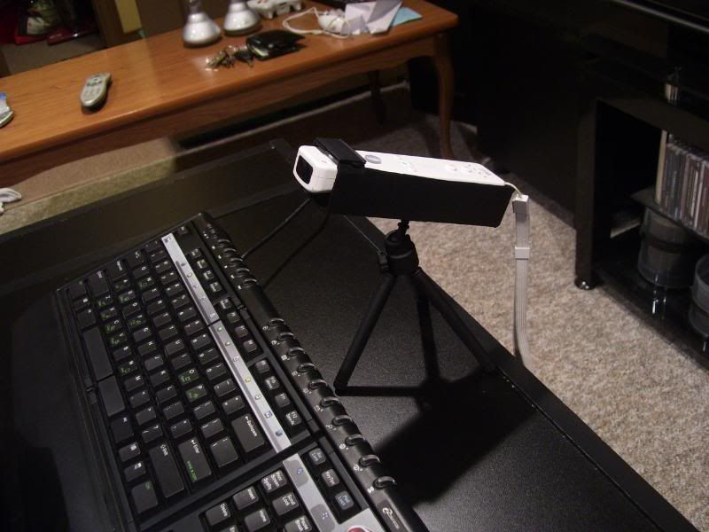 And I built a new Free-Track cap that is wireless and more comfortable... 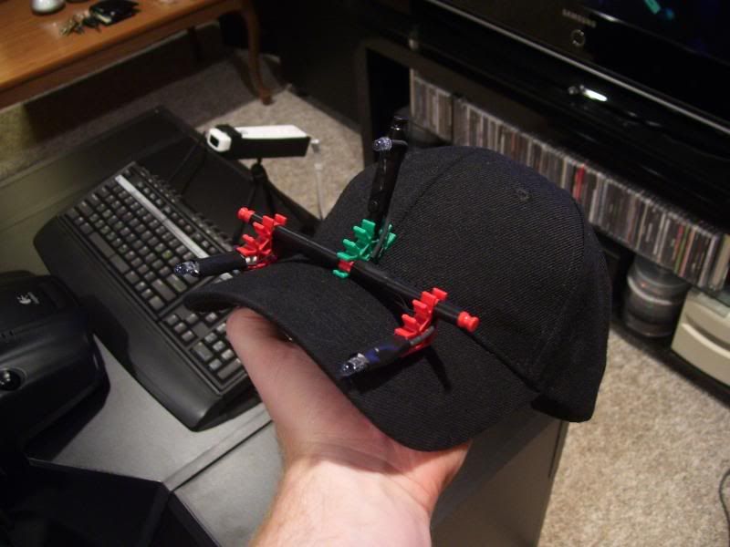 And here it is powered by 2 AAA rechargable batteries and a power switch. 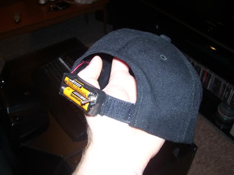 Nothing else... maybe I'll make a youtube video showing it in action... |
| Wermut | #100 26/09/2009 - 21h02 |
|
Class : Apprenti Off line |
Follow this link for pictures of my rig!
http://img269.imageshack.us/gal.php?g=dsc00601rj.jpg Details: 3 Osram 485 IR leds (100mA draw) 1 plain red indicator led (20mA draw) 2 ohm resistor (for the 3 osrams in series) 330 ohm resistor (for the red indicator led) 2A picofuse (smallest one I could find locally... probably overkill) USB powered, 4.5 volts. The resistors, fuse and red led sit in a battery box (which was convenient because it has a switch) The frame that the IR leds are on is insulated copper wire.. not sure of the gauge but it's pretty thick. For aesthetics I've shrink tubed most of it. And finally, I can quickly disconnect myself to move around my room - I found a charging cable for a cell phone at a local surplus store (usb on one end, thin plug on the other) and asked for a matching female end to plug it into. That's about it!
Edited by Wermut on 29/09/2009 at 02h55.
|
| VectorRoll | #101 06/10/2009 - 20h22 |
|
Class : Apprenti Off line |
Here are a few pictures of mine. I messed around a few times to get use to it before I finally came up with this design in the end. I tried to get the diode placement as close as possible to the design in the tutorial.
My brother had a roll of 500 of these red diodes, so I used them for now.  The shafts are just your basic ball point pen tubes. The battery holder is made of cardboard with black tape. The center joining peace is actually the butt end of an XBox DVD remote. The remote no longer worked. I cut the end off and used a dremel to cut the holes for the tubing. I used two paper clips for the mounting bracket. All the wiring is soldered except for the battery. I may putt a small on/off switch on it later on. I noticed that they say to use resisters. I have a few but did not use any for this setup. To explain, the diodes are just daisy-chained to the 9v battery. I tried AA, from 2 to 6 of them, with the resisters like in the tutorial and it would not light up all three diodes at the same time. I think it has to do with the diodes I am using. I am not sure what the exact rating of them. It is not listed on the roll. That is why I just went with a straight 9v connection. The camera I am using is the Logitech Orbit AF. I also use the film from a 3.5 floppy to cover the lens.       So far from testing it in the application it seems to work fine. I have yet to try it in a game. I want to find a way to map it to the Free-look controls, but PPJoy does not work in Windows 7 so I need to find an alternative or a way to make it work. |
| R2D2 | #102 14/10/2009 - 13h01 |
|
Class : Apprenti Off line |
Just a first try, works good so far, angles are not perfect. Those are 5V LEDS - some blue ones i got from lighters with light
 Power comes directly from USB The case was a Scart-plug Next version is being made (the 4. device im building) pictures to come soon.        Dont blame me, it's the first try and it works :-) (up to 30degree ;-/)
Edited by R2D2 on 14/10/2009 at 13h02.
|
| twrdkosh | #103 17/10/2009 - 11h56 |
|
Class : Apprenti Off line |
few construction with LED:
http://www.youtube.com/watch?v=foThOcIRaAw |
| Salvaje9 | #104 17/10/2009 - 15h37 |
|
Class : Apprenti Off line |
I went to RadioShack purchased 5 mm Ir led's and made this out of plastic.
 
Edited by Salvaje9 on 17/10/2009 at 19h16.
|
| benmeijer | #105 09/11/2009 - 21h36 |
|
Class : Habitué Off line |
My latest Clip build with 3 leds (SFH485P ) and one resistor (5v USB powered)
Found some material in my garden  cut it in a smaller part  put small holes in the legs for the leds (SFH485P)  leds wired (serial)  connected to USB cable (with 1 resistor in the + wire)  connected between 2 small round platters  checked dimensions in cm (for freetrack configuration)  ready   how I connected the clip to my headphone with velcro (can take it off anytime)  |
FreeTrack Forum > FreeTrack : English Forum > Support : Tracking System > Your point model constructions
> Stats
1 user(s) connected during the last 10 minutes (0 member(s) and 1 guest(s)).
Powered by Connectix Boards 0.8.4 © 2005-2024 (8 queries, 0.028 sec)