FreeTrack Forum
FreeTrack Forum > FreeTrack : English Forum > Support : Tracking System > Your point model constructions
| Waldo_II | #76 12/04/2009 - 05h35 |
|
Class : Apprenti Off line |
I have yet to try this out in a game, or anything other than Free Track for that matter, but so far it looks like it is going to work very well.
I took a cheap CD case and cut it up with a Dremel tool, then hot glued some pen tubes (I removed the ink, the tip, and the end) to it, then soldered some IR LEDs to wire, ran those through the pen tubes, and soldered all positive wires together and the negatives together. I ran those to a battery on the top of the headset. There is also a switch that I threw in there, you might not be able to see it in the picture. I decided that the cut-up CD case base was too close to the headset, so I took the little plastic casing that CompactFlash cards (like for your digital camera) come in, put some electrical tape around the ends to make it look cool, and then hot-glued that case to the cut-up CD case base. My headphones have a point where it pivots; when the base was attached directly to the headphones, it collided with the top strap of the headphones, which knocked it around. The battery pack and the cut-up CD case are attached to the headset via strips of velcro (the other side of the velcro has adhesive on it).     This is how it looks to the camera. VX-1000 with the IR filter removed. The lights in the room were mostly off, dimmed to about 30%. 
Edited by Waldo_II on 12/04/2009 at 22h39.
|
| oakdesign | #77 03/05/2009 - 21h37 |
|
Class : Apprenti Off line |
So here is my story:
Having a bank holiday on friday I cleand up my home office and found my old Falcon 4.0 CD wich I haven't used since 2006. After doing some reaserch on news to the Sim I found your excellent site so I decided just to start to build my Free Track point model. Saturday morning I went to our local DIY market and bought a bicycle ligning Kit containing of a 5 white LED front lighter - flashlight style and a backlighter with red LED as used by some other people here. Next I went to our toy store as that was the fastest to get a Webcam bought a Labtec 2200 After some installation issues with the webcam, I'll post that in the camera thread I firt tried out the results for the red and white LED, so the red were to weak so I decided to go on with the white ones. Here are the results: Sorry for the Quality but my "big" Cam is borrowed by my brother at the moment. Cap with LED turned off  Cap with LED turned on  Detailed view of LED fixation  Mini poard of the flashlight where I soldered of the LED already having the resistors on it and power supply cable so that the batteries are not to placed on the Cap  Power Supply with on and off 4 AAA  So this was my first very Qick attempt. Next improvment will surly be to move from IR LED and 9V or USB power supply |
| Letum | #78 06/05/2009 - 13h04 |
|
Class : Apprenti Off line |
I have since made a proper mounting for it.
The top mounting position works fine.  |
| EDcase | #79 08/05/2009 - 18h03 |
|
Class : Apprenti Off line |
Just finished and works great with cheapo Philips SPC300NC/00. No filter needed.
3 green LED Bicycle light from Tesco £1.25 (Same one used by Jewcookie  ) LEDs filed flat. ) LEDs filed flat.Plasic clipboard from Tesco (no pic) £2.50 Total £3.75  Other things used: modelling drill, hack saw, superglue, soldering iron Original light:  Parts: Remove silver reflector. de-solder LED very carefully not to cook em.  Internals  Back with on/off button.  Front view with clip mount. (I may try velcro instead of the clip)  Dimensions: (Copied from a certain company making the same thing  ) ) Thanks to my modelling assistant 
Edited by EDcase on 09/05/2009 at 23h29.
|
| JAGUAR | #80 14/05/2009 - 04h34 |
|
Class : Apprenti Off line |
Hi, this is my design, the main idea on it was the option to dismount the base for the led's from the cap, to allow the cap to be washed.
 The base was made from a dvd case, and it have clips on the side to attach it to the cap. The leds are connected to an audio cable that comes with almost any dvd or cd-rom, two cables were used. The leds could be also be mounted or dismounted without soldering, just by inserting the leds on the connector. The battery case and the circuit box are attached to the cap with velcro. This is the webcam used, a VX-1000 with the filter made from a diskette, and with the internal IR filter not removed, it works fine.  The cap with the leds on  The base for leds dismounted. The switch is not working, it was planned to be used, but it was faulty since the begining and I don't have time to buy another one, so I finish it without it, and leave it attached to the battery case.  The circuit box  The cap and the batteries 
Edited by JAGUAR on 14/05/2009 at 17h22.
|
| leandroter7 | #81 20/05/2009 - 14h20 |
|
Class : Apprenti Off line |
Hi guys.
I´ve create this desing, and some friend's of mine, put some orders with me. I ve been sale more then 10 pieces of mine Track clip (TREKO CLIP) TREKO in portuguese, is something about "simple stuff". Note. Before this, i never try use wellding devie in my life. My Treko Clip, have a USB cable. Avaliable on net for just usd$ 50,00..... I will do a donation for free-track soon. hehehehehehehe   With best regards Leandro Tercette
Edited by leandroter7 on 20/05/2009 at 14h23.
|
| E111Bellota | #82 27/05/2009 - 11h07 |
|
Class : Apprenti Off line |
the ir led is the best for the wii mote. the wii mothe is de best camera for the leds infra red.
no interferences.
Edited by E111Bellota on 27/05/2009 at 11h08.
 |
| crunchysaviour | #83 04/06/2009 - 17h39 |
|
Class : Apprenti Off line |
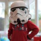
Hello there, ladies and gentlemen. This is what I will now call THE HAT:
Stuff I had to buy: - Resistors x3 50 ohm: 45p total - Resistors x3 30 ohm just in case - 45p total - AAA battery holder - 60p - Switch - 70p - LEDs x5 (minimum quantity was 5, but free postage!) - £2.60 Total: £4.90 ish. Stuff I had already: - 2x AAA batteries - Old baseball cap - Ty-raps, solder, soldering iron, electrical tape, gaffer tape, piece of aluminium for the top LED, tools etc. I am using a Wiimote as the camera, connected with BlueSoleil via my laptop's built-in Bluetooth hardware. I get 1.4V, 42mA across each LED as read from the multimeter.   1. The parts. Note the wire - I ended up using some much beefier wire. I didn't trust how thin the wire in this photo was. 2. Soldering a 50 ohm resistor to the +ve leg of each LED.   3. Soldering wire to the resistor/LEDs, so I can put them where I want. 4. LEDs lengthened with wire. Now I have twisted the +ve ends together with the +ve wire from the battery. The -ve ends are all twisted with the -ve wire from the battery (via the switch). Try it with a multimeter and in front of the Wiimote - to make sure it works before soldering it together.  5. Soldering together one of the main junctions. It's hardly elegant but it's easy to understand.   6. THE HAT as it is (unfinished but working!). The front LEDs are taped on. I will make this more permanent tomorrow, maybe. 7. The top of THE HAT. See the Ty-Raps poking out where I've secured the battery box etc. The top LED is taped to a piece of 1mm aluminium sheet for support.   8. Finished hat. Front LEDs now attached with Ty-Raps. 9. Finished hat, underside view. The front LEDs poke through holes in the front of small plastic brackets that I made by cutting, scoring and folding pieces from a thick plastic ice-cream tub (the translucent type, not the cheap white type). This guards the LEDs from damage when the hat is resting. Dimensions of the LED triptych: H 80 mm L 100 mm W 125 mm (half width 62 mm in FreeTrack) FreeTrack gives FPS close to 100 (the magic of the Wiimote!) but jitter is high, between 40 and 60 JPS usually. I usually have the threshold at about 25%. I'm using averaging of 20 and smoothing of 30. I have also edited the curves so the tracking is less sensitive near the centre. I have now tried both the Wiimote and hat with NiMh rechargeable batteries, and both work, albeit probably not for quite as long as with alkalines! I will try timing them soon.
Edited by crunchysaviour on 19/06/2009 at 10h19.
|
| overkill | #84 08/06/2009 - 12h13 |
|
Class : Apprenti Off line |
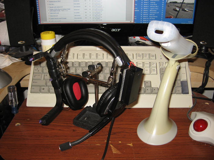
My three point "cap" setup fitted to my headphones:
    All powered on at night:  Again batteries in, this time with camera flash on:  Close up of the wiring tucked in to this set of headphones:   Not bad for a cheap set of headphones which has the wiring groove built in, three biro pen tubes, black electricians duct tape, three IR LED's, three resistors, a AAA battery holder, Superglue, and two AAA rechargable batteries!!!! |
| Gravata | #85 09/06/2009 - 05h36 |
|
Class : Apprenti Off line |
Strangely familiar ;D... |
| TAZ | #86 10/06/2009 - 18h50 |
|
Class : Apprenti Off line |
Nothing major. Used the hanger wire, soldered together at the cross, for structure, as described in the handbook and balsa wood and crazy glue for led mounts. LEDs came with pre-wired resistors and were enclosed in a threaded casing which I screwed into the balsa. LEDs were wired to a battery box setup for 2-AA batteries which is located in a hidden velcro pouch behind the bill. This came with the cap. Golfer perk I guess.
Webcam is a Logitech QuickCam Connect. Very compatible at 31fps and did not have to use film or remove ir filter. The exposure settings were all that was needed. Response is instant even with a light on in the room. Total cost was in at $45 not including hat which was in the closet which about 15 other hats.     
Edited by TAZ on 10/06/2009 at 18h53.
|
| Forgotten_Illustrator | #87 12/06/2009 - 23h55 |
|
Class : Apprenti Off line |
Well first of I would like to say thanks for a get little program.
Now I would like to share with you all my 3 point cap which has a pressure sensor in the cap so it is only active when youre wearing the cap. Its not as fancy as it sounds, its just a momentary micro switch in the inner liner of the cap. General view of cap. 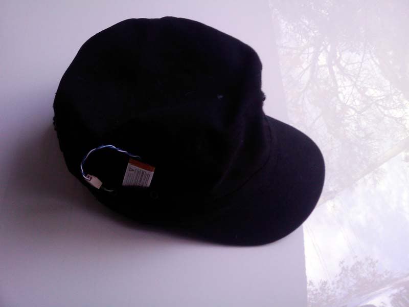 Front view  Inside, board view 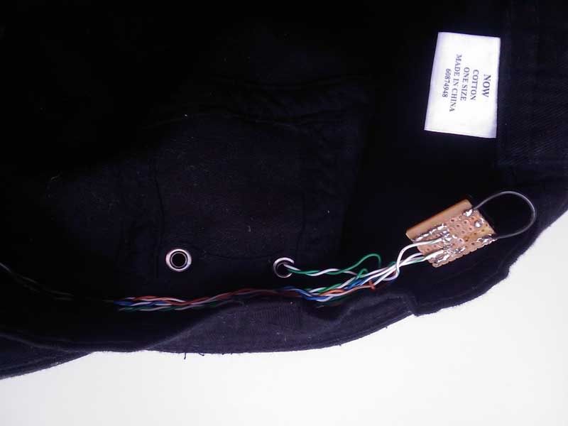 Other side of board with the 3 resistor(in parrel) and switch 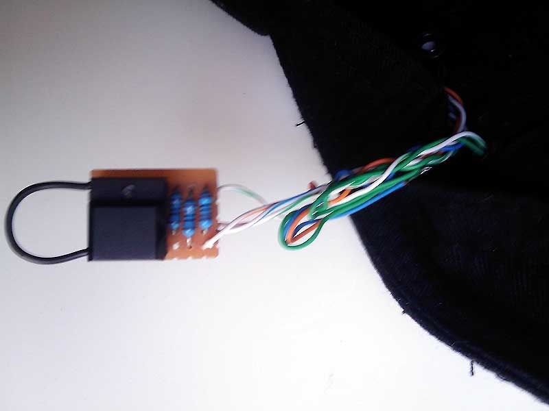 powered by a rechargable Ipod nano Battrey 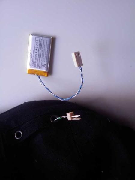 Was my first constuction, just didn't like it sitting on my ear so when out and made the cap above. 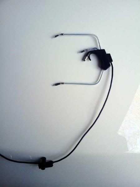 |
| mrclean816 | #88 25/06/2009 - 23h04 |
|
Class : Apprenti Off line |
And my now perfectly functioning ir tracking setup.
    |
| mrclean816 | #89 02/07/2009 - 00h25 |
|
Class : Apprenti Off line |
My 3 point model.
No batterys and larger size to accommodate better tracking and identification of leds.      |
| rforeman | #90 04/07/2009 - 17h41 |
|
Class : Apprenti Off line |
Here is mine I just finished last night.
Edited by rforeman on 04/07/2009 at 17h45.
|
FreeTrack Forum > FreeTrack : English Forum > Support : Tracking System > Your point model constructions
> Stats
1 user(s) connected during the last 10 minutes (0 member(s) and 1 guest(s)).
Powered by Connectix Boards 0.8.4 © 2005-2024 (8 queries, 0.061 sec)