FreeTrack Forum
FreeTrack Forum > FreeTrack : English Forum > Support : Tracking System > Your point model constructions
| Max War | #61 18/01/2009 - 20h38 |
|
Class : Apprenti Off line |
Hi all,
here is my 3 point model construction (it is a rebuild from the "DIY 3 Point Clip for FreeTrack Tutorial" which you can find on googlevideo). It is very small and the weight is only a few gram. I put a hook an loop fastener on it to have an easy way to put it on my headset. 2 x batteries AAA 1,5Volt (LR03) 3 x IR-emitter (I removed them from a old zapper) the smal tubes are from an old ballpen     This is a very light and compact system that you can easily build by yourself. For more information watch the video on google. Have fun! Max War
Edited by Max War on 18/01/2009 at 20h40.
|
| chair | #62 26/01/2009 - 04h51 |
|
Class : Apprenti Off line |
Edited by chair on 26/01/2009 at 04h54.
|
| babasior | #63 26/01/2009 - 11h48 |
|
Off line Www |
Babasior.
FreeTrack Online / www.Free-Track.net |
| E111Bellota | #64 30/01/2009 - 13h10 |
|
Class : Apprenti Off line |
my wiimote suport construction
  My Cap whit led IR, the power is one old charger of movil thelephone    |
| TurkishG | #65 14/02/2009 - 15h59 |
|
Class : Apprenti Off line |
And this is my 3 point cap... I know it is ugly but it isn't made to be pretty
    Battery bays and power switch....   |
| jamitgze | #66 04/03/2009 - 00h14 |
|
Class : Apprenti Off line |
Overview
Hi folks, so far my focus has been on the power supply for the 3-point cap. I used an old/dead Nokia 6233 mobile phone as the basis which gave me a 3.7v (actually 3.9v) rechargable battery (Lithium-Polymer BP-6M) that I could recharge with a standard nokia charger. Using the mobile phone as a shell gave me a lot of space to install everything ie. 3 x 150 Ohm resistors, power/charge switch, etc. After the initial build, I upgraded my setup with a mini-PCB-mount 5-pin plug/socket for the headset that I mounted in the micro-SD hole. I can now disconnect the cap, close the micro-SD cover and take the phone to a charger in another room without having to carry the cap around. I can also use this setup to power other projects without having to build another power supply! Build Sequence 1. Gut the mobile phone (you'll need a special mini-hex driver and optionally a small pry bar that I got when I ordered a replacement cover).  2. Solder 5cm long black (-) and red (+) wires straight onto the battery terminals (unfortunately trying to retain the battery contacts is far too difficult so the battery needs to be permanently mounted). Solder 5cm long black (-) and red (+) wires onto the charge terminals. the point closest to the edge is positive and the point near the bottom connector is negative.  3. Install and glue either a SPDT or DPDT mini switch into the space on the bottom of the phone (where the connector used to be). You will need to snip ount a little plastic ridge where the pins go otherwise the switch won't sit flush with the back case.  4. Make up the resistor setup based on the LEDs you are using. I used 3 x 150 ohm resistors as I am using the Dick Smith IR LEDs (Z-3235 1.2v 20mA). Simply solder one end of the resistors together.  5. Solder the red (+) wire from the charger socket to the pin closest to the charger socket. Solder the red (+) wire from the battery to the middle pin. Solder a 5cm red (+) wire from the joined end of the resistors to the pin on the end of the switch on the opposite end to the charger socket. 6. Solder 3 x 5cm red (+) wires from the 3 loose ends of the resistors to your cap/headset socket. Alternatively, solder 30cm lengths of red (+) wire if you are not going to use a plug/socket for the headset. Heatshrink each of the 3 joins separately and then heatshrink all 3 resistors together.   7. Solder the two black wires (charging socket and battery) together. Then solder a 5cm length of black (-) wire and solder the other end of the wire to your socket. Alternatively, solder a 30cm length of black (-) wire if you are not going to use a plug/socket for the headset. Note: I have a spare 5cm black (-) wire in my phone for future enhancements :-). 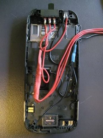 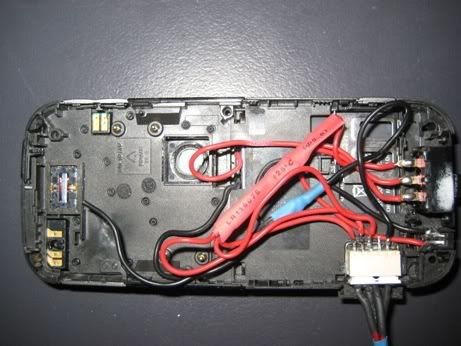 8. Clip and screw the case back together. You may need to cut a small amount of the cover above the switch and the cap headset socket so it closes fully. You may also need to glue the button keypad to the cover as it usually is held in-place by the circuit board which was removed. Optionally print-out and stick a Free Track logo to the inside of the screen ;-).   All done! Then simply follow any of the excellent instructions posted in this forum to build your cap headset. |
| Lord_Nothing | #67 13/03/2009 - 14h42 |
|
Class : Apprenti Off line |
i kinda built something a little different
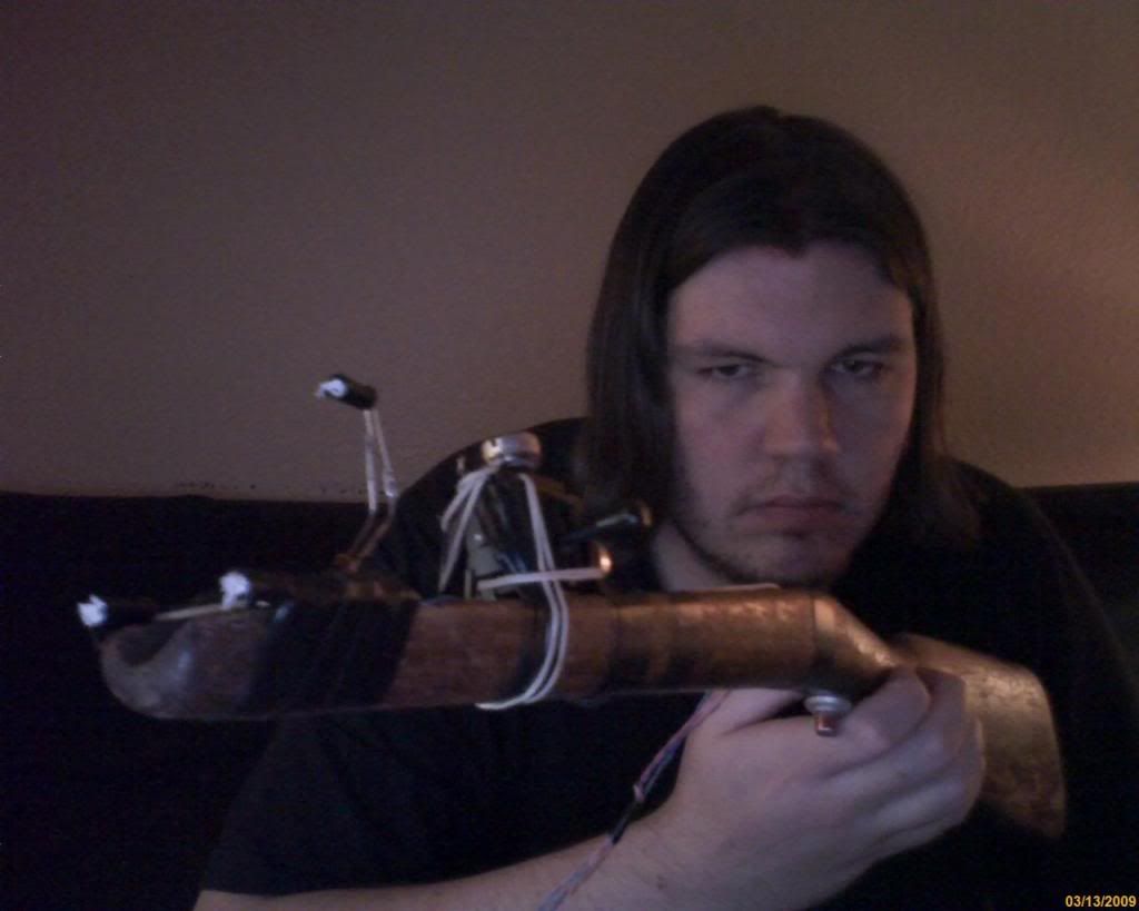 i came up with the idea when i found the rifle butt in the dumpster. i thought, if i put some leds and a joystick on that think, id have the perfect controller for quake. im using one of these to interface the joystick and "trigger", as well as powering the leds. to play in quake (actually im using the dark places engine), i wrote a cfg to use the joystick as walk and straig while moving the gun around aims the player. im thinking about taking it a step further and making it possible to control the in-game weapon orientation and position proportionally to the guns position in the real world. this of course requires i modify the game engine. but first i need to understand how to talk to the interface dll. right now im having trouble getting the sample c code to compile a working exe (im using vc2008 express). my first compile generated "ERROR: unable to find 'FTReportID' function". i looked through the delphi code (a language im not at all familiar with, i mostly use c, c++ and lua) and found that it calls the function FTReportName and not FTReportID. i assumed this was a typo or something. after that i could sometimes get some output for a few seconds then it would crash. other times it would just crash out right. il play with it some more later. |
| epokh | #68 13/03/2009 - 19h48 |
|
Class : Apprenti Off line |
I used the wiimotekit and did my 3 point cap model.
 The kit is made by laser cutting. The list of distributors is on this page The UK retailer sells the kit here
Edited by epokh on 14/03/2009 at 23h01.
|
| Jewcookie | #69 18/03/2009 - 20h40 |
|
Class : Apprenti Off line |
This is my 3point model.
Made it from a bike LED light and some chopsticks. I usually click it on my headset or cap.  Works pretty well. But i hope i get my IR LEDs tomorrow so i can use my Wiimote!  |
| Bloopyboy | #70 20/03/2009 - 12h13 |
|
Class : Apprenti Off line |
Edited by Bloopyboy on 20/03/2009 at 12h14.
|
| CyBeRpUnK_CRO | #71 23/03/2009 - 11h25 |
|
Class : Apprenti Off line |
This is my 3 point side head ir transmiter:))
 
Edited by CyBeRpUnK_CRO on 23/03/2009 at 11h29.
|
| Karin | #72 23/03/2009 - 20h57 |
|
Class : Apprenti Off line |
I didn't want something that looked goofy, so I tried to integrate the 3-LED setup into a cap as best I could, using minimalist techniques to hide just about everything. Also, all of this is reversible meaning I can later take everything off of it and have a perfectly normal, undamaged hat.
Here's the hat, showing each of the three infrared LEDs. I affixed the wires leading to the front LEDs with velcro, which you can see poking out on the right and in subsequent photos. It holds the wires in place and allows for easy access in case I need to change anything. 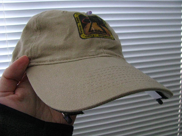 Top view of the hat is shown below. You can see in the hat logo that I hand-stitched some of the internal wiring to hold it into place, and didn't have the correct colour for the logo itself. Everywhere else though the thread colour matched up almost perfectly. 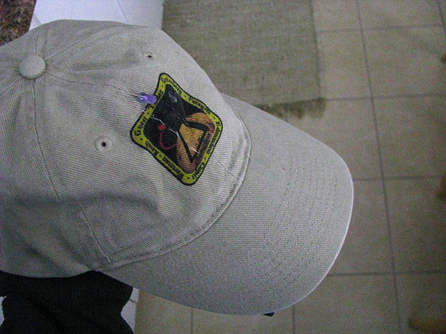 Below image is the inside view. I used one AA rechargeable battery in a plastic battery holder I got from the same place as I bought the LEDs, which is more than enough power for 7-8 hours of gameplay I figure. I would have preferred to use an AAA size battery to keep it smaller, but there were no plastic cases available for that size. Sticky-back velcro strips (available at sewing supply stores) hold the front wires in place while allowing easy access for if/when I need to change anything, without ruining the hat. 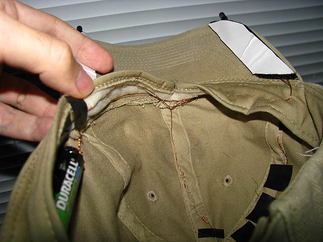 Below image shows how I wired the hat. Bare copper wire (bought from Wal-Mart) was stitched into the inside of the rim of the hat, with electrical tape used as needed. The biggest problem with bare wires is short circuiting it if they touch each other. I had to be mindful of where wires were stitched, and where to put electrical tape for some insulation. 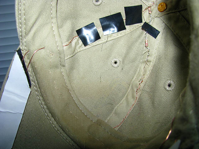 Below is my gaming rig, an Apple MacBook Pro 2.5GHz w/ 4GB DDR2 and an nVidia 8600GT w/ 512MB video memory. I used two layers of film negative taped over the built-in webcam, visible as a black square along the top rim of the screen. I haven't removed the webcam's IR filter, and it still works fine. The only problem is I'm limited to 15fps, but I'm working on using a Wii controller. The game shown is Evochron Legends (click for link). 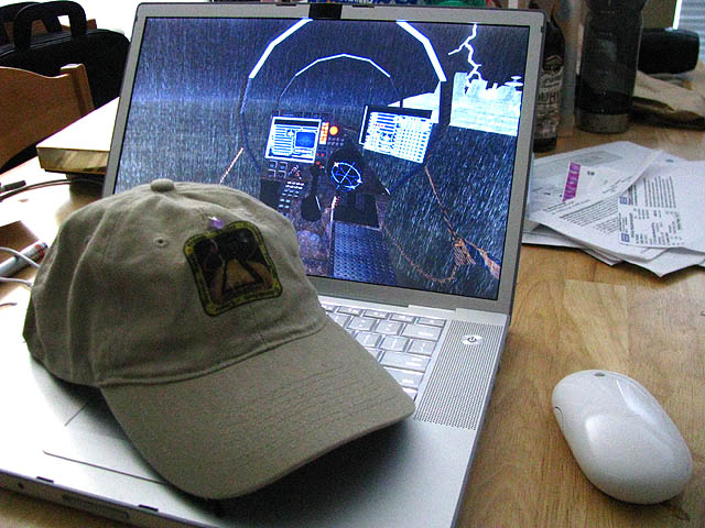 |
| rox | #73 25/03/2009 - 23h45 |
|
Class : Apprenti Off line |
This should come as support for those without gear like soldering irons or knowledge in this electrical stuff, like me.
The budget 3 point clip, made from: 3 IR leds 2 ordinary pencils wire electrical tape Works like a charm, at least in front of the cam, didn't test it with freetrack, I'll do that when I get home for the weekend. 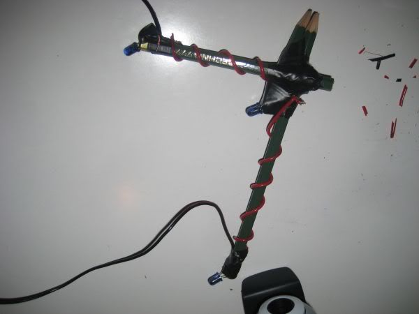 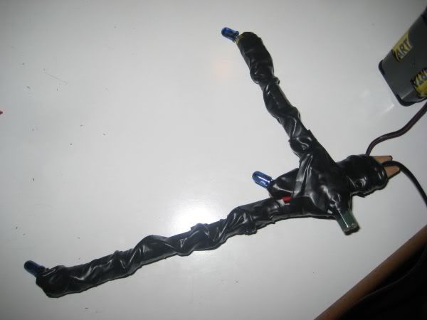 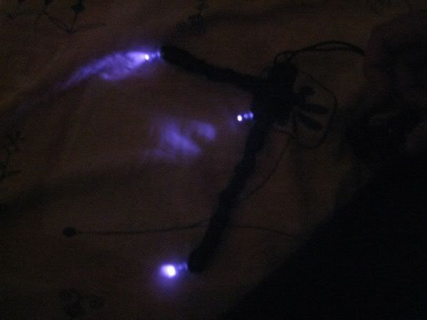 |
| mav1985 | #74 26/03/2009 - 16h00 |
|
Class : Apprenti Off line |
Some german Aerospace-Engineers have developed this smart non-electric solution for people having trouble buildung a tracker with LEDs
  the tracker...  ...in action ...works like a charm!!! |
| Fanboy1337 | #75 09/04/2009 - 12h25 |
|
Class : Apprenti Off line |
I created a 3 point clip with a 2.4V power supply (2x rechargeable AA) and 3 SFH485P LEDs.
 Took me about 3 hours  because I have never ever soldered before. because I have never ever soldered before.But it works and it's not as ugly as I had feared. The frame is made of plastic card and plastic sprues so it is ultra leigth weight.
Kind regards from Germany.
Setting up my Freetrack for www.jumpgateevolution.com |
FreeTrack Forum > FreeTrack : English Forum > Support : Tracking System > Your point model constructions
> Stats
1 user(s) connected during the last 10 minutes (0 member(s) and 1 guest(s)).
Powered by Connectix Boards 0.8.4 © 2005-2024 (8 queries, 0.024 sec)

